The store will not work correctly in the case when cookies are disabled.
-Kmw.png)
Litter-Robot 3: Pinch & DFI kit installation guide
Litter-Robot 3 is equipped with infrared emitters and sensors, called
the Drawer Full Indicator (or DFI), located above the waste drawer. The DFI
checks if the drawer is full each time the globe returns to the home position.
Litter-Robot is also equipped with an anti-pinch safety feature. While
cycling, if a potential pinch condition is detected, the globe will stop and
reverse direction for 2 seconds. The yellow light will begin flashing quickly
awaiting your action.
The DFI and anti-pinch safety feature share the same assembly. Learn how to replace the DFI board assembly and pinch contacts below.
Kit includes:
- DFI board assembly
- DFI housing
- (4) screws
- (2) pinch contacts
Tools needed:
- 6-inch (15 cm) #2 Phillips screwdriver
- Flathead screwdriver
- Needle-nose pliers
Preparation
-
Press the Power button to turn the unit off.

-
Unplug the power plug from the base.
-
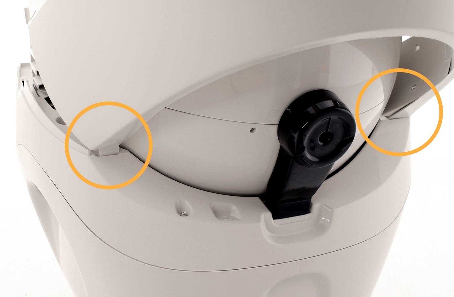
Press the bonnet tabs on either side of the unit to release the bonnet.
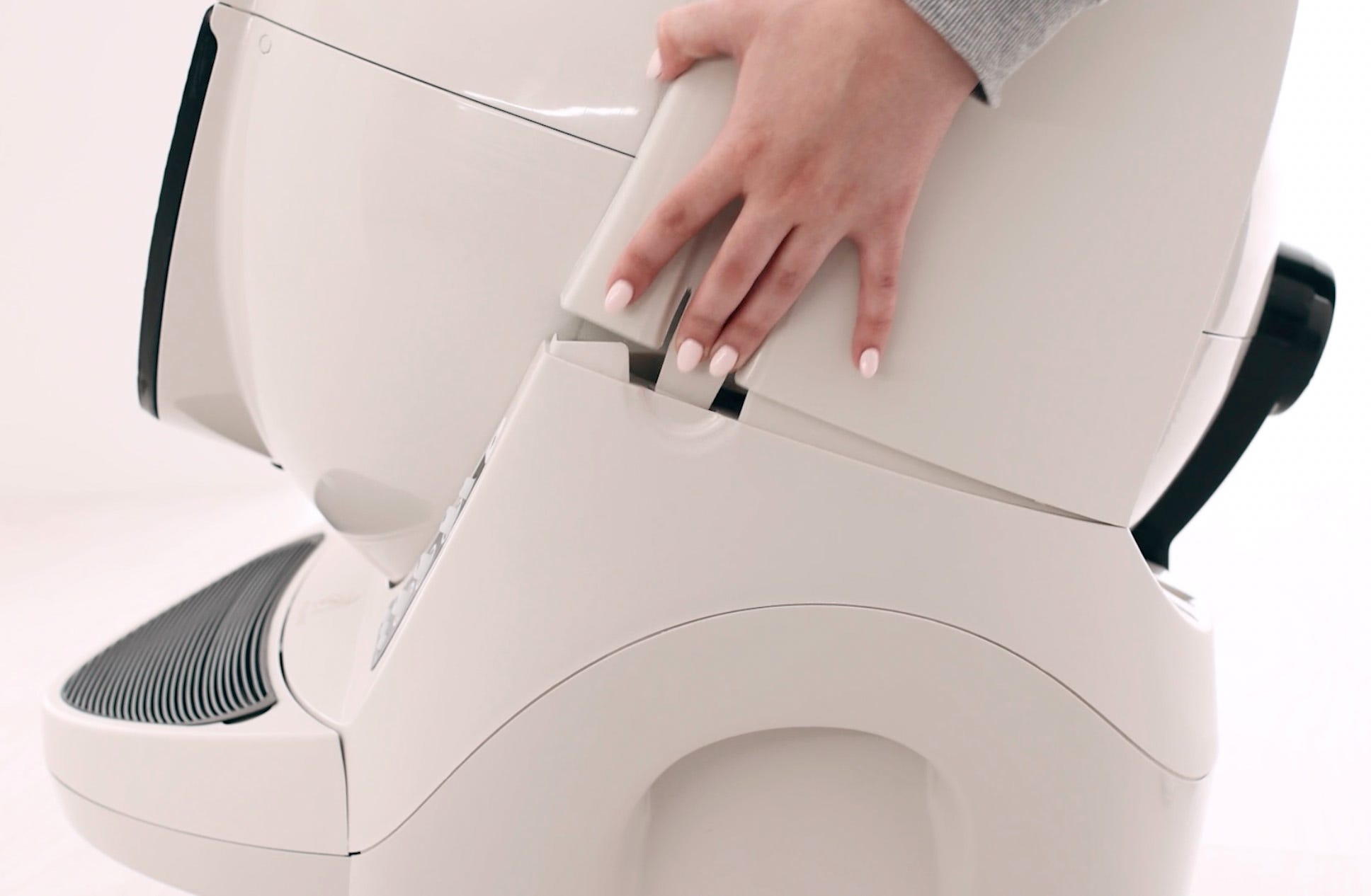
-
Rotate the bonnet backward and lift the bonnet up to remove it from the
unit.
-
Remove the globe and set it aside.
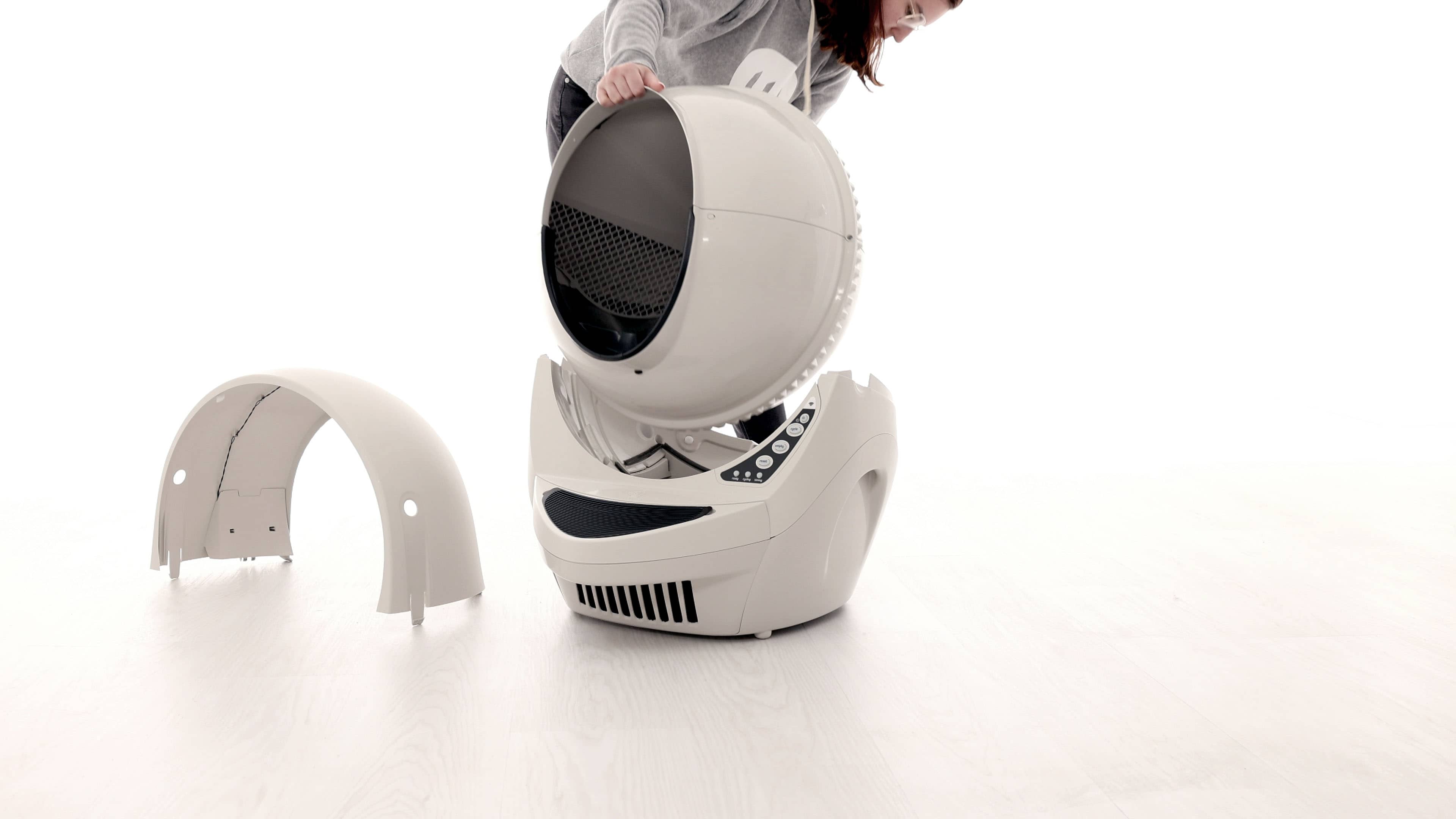
-
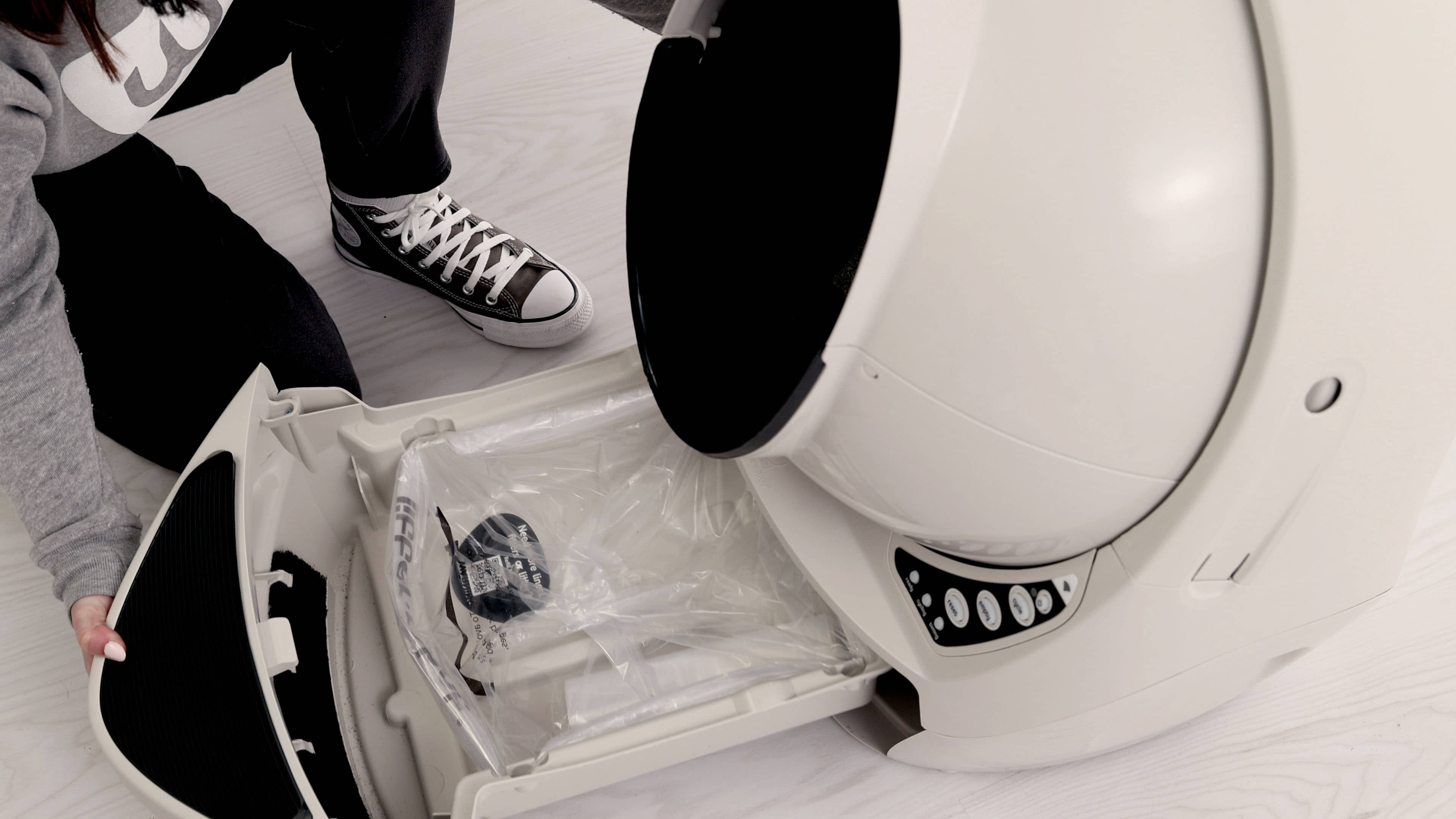
Remove the waste drawer and set it aside.
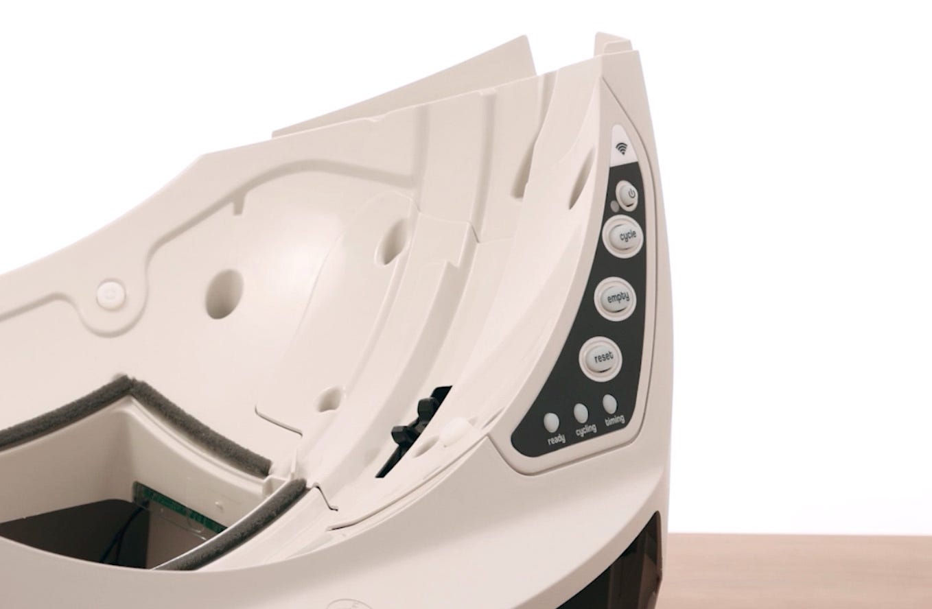
-
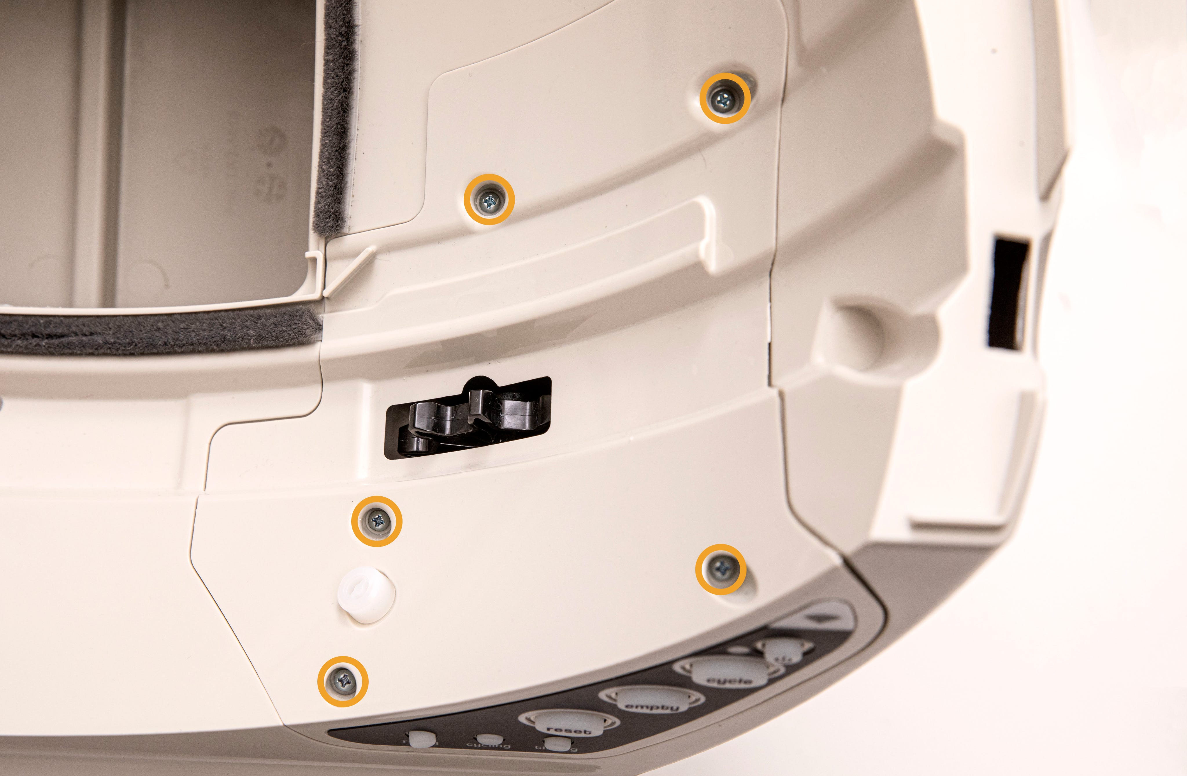
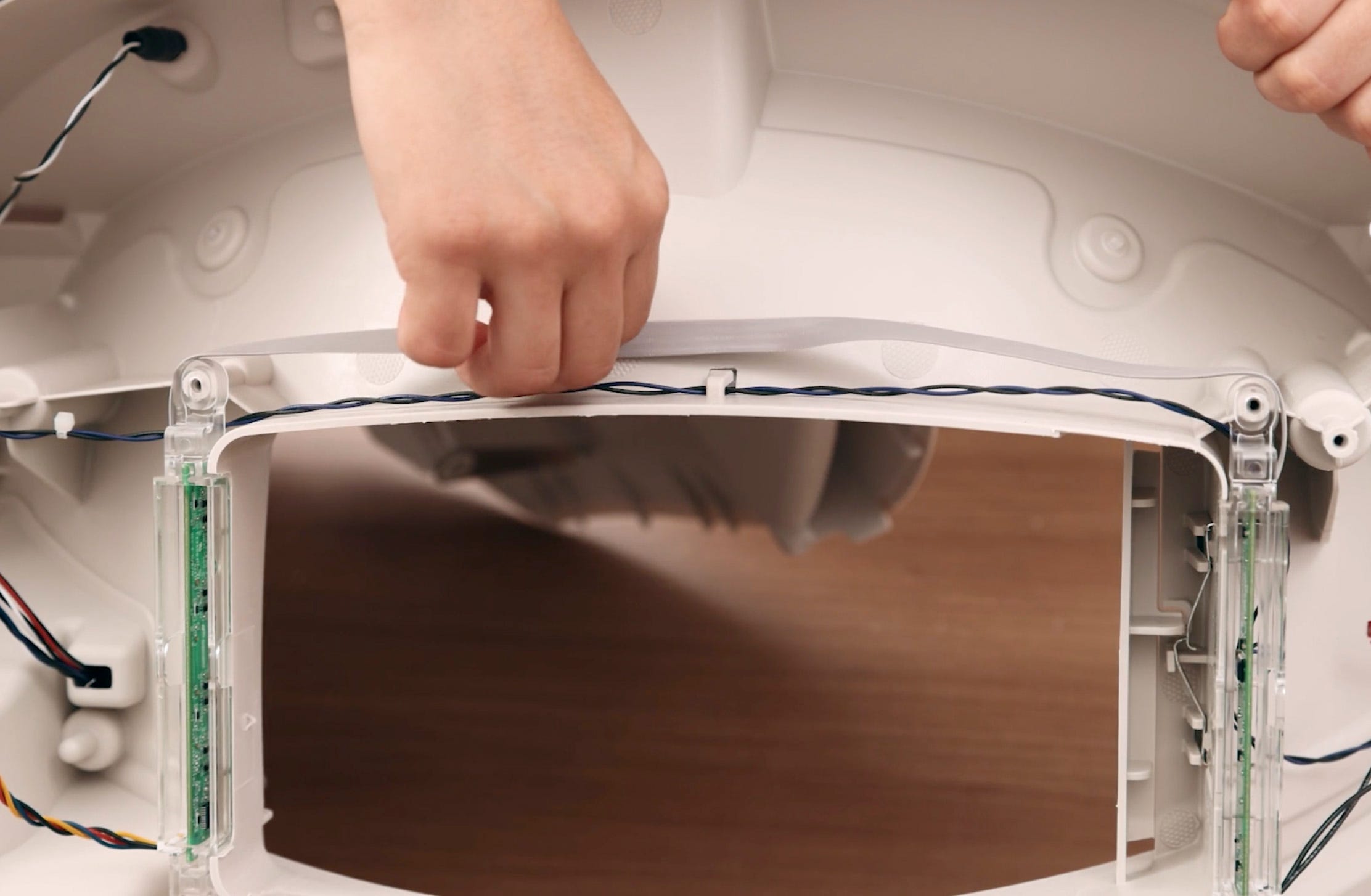
The plastic component that covers the control panel on the base is called
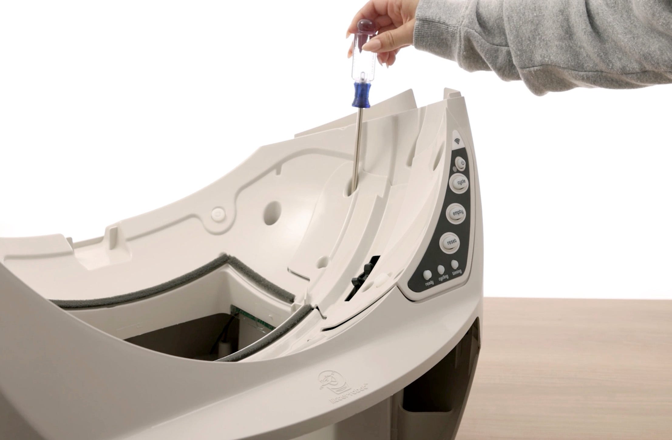
the control panel cover. Unscrew the 5 screws to remove the cover.
-
Use needle-nose pliers to lift the cover out of place.
-
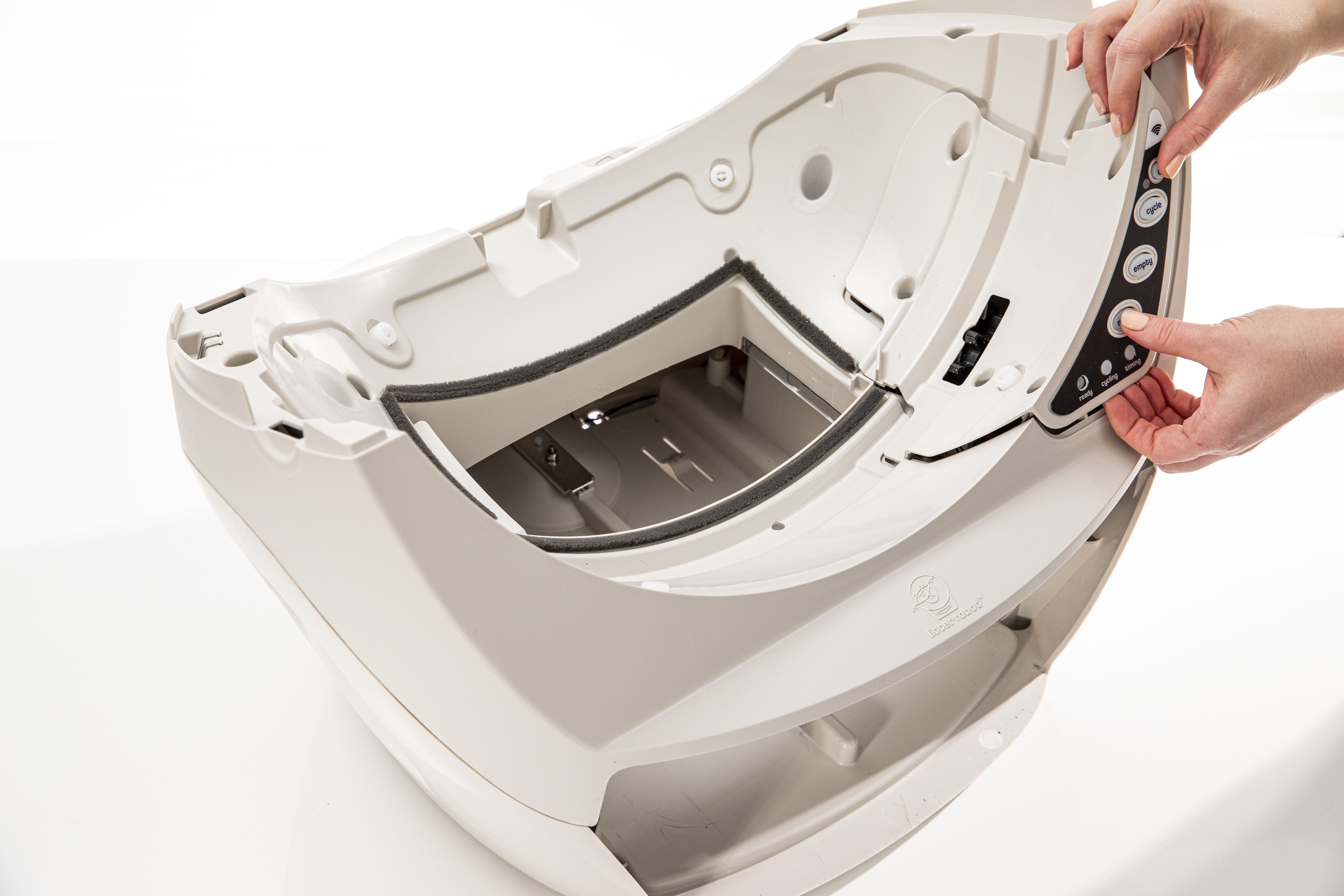
Separate the control panel cover from the control panel by pushing the
buttons through and lifting up. Set the control panel cover and screws
aside.
-
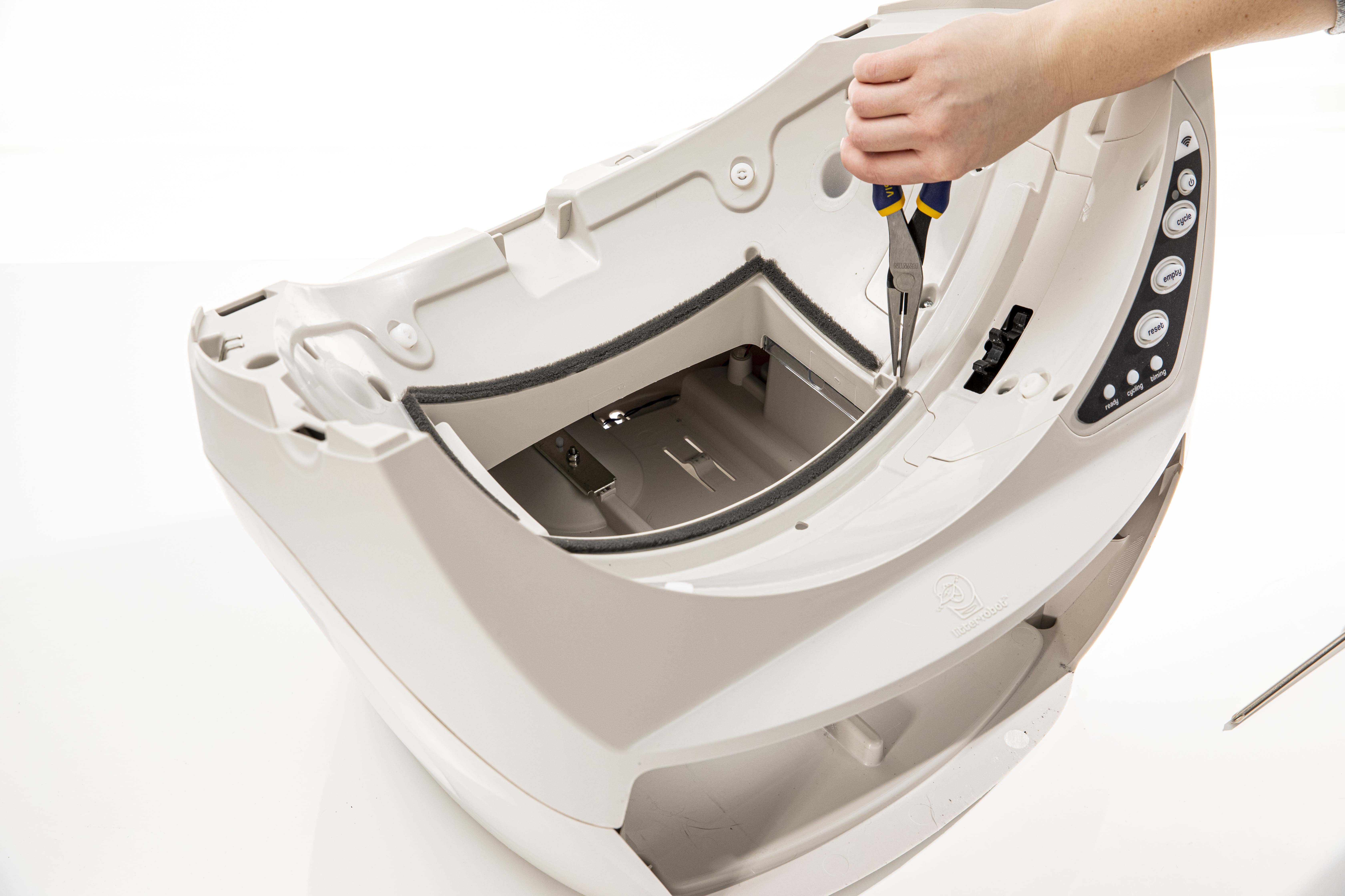
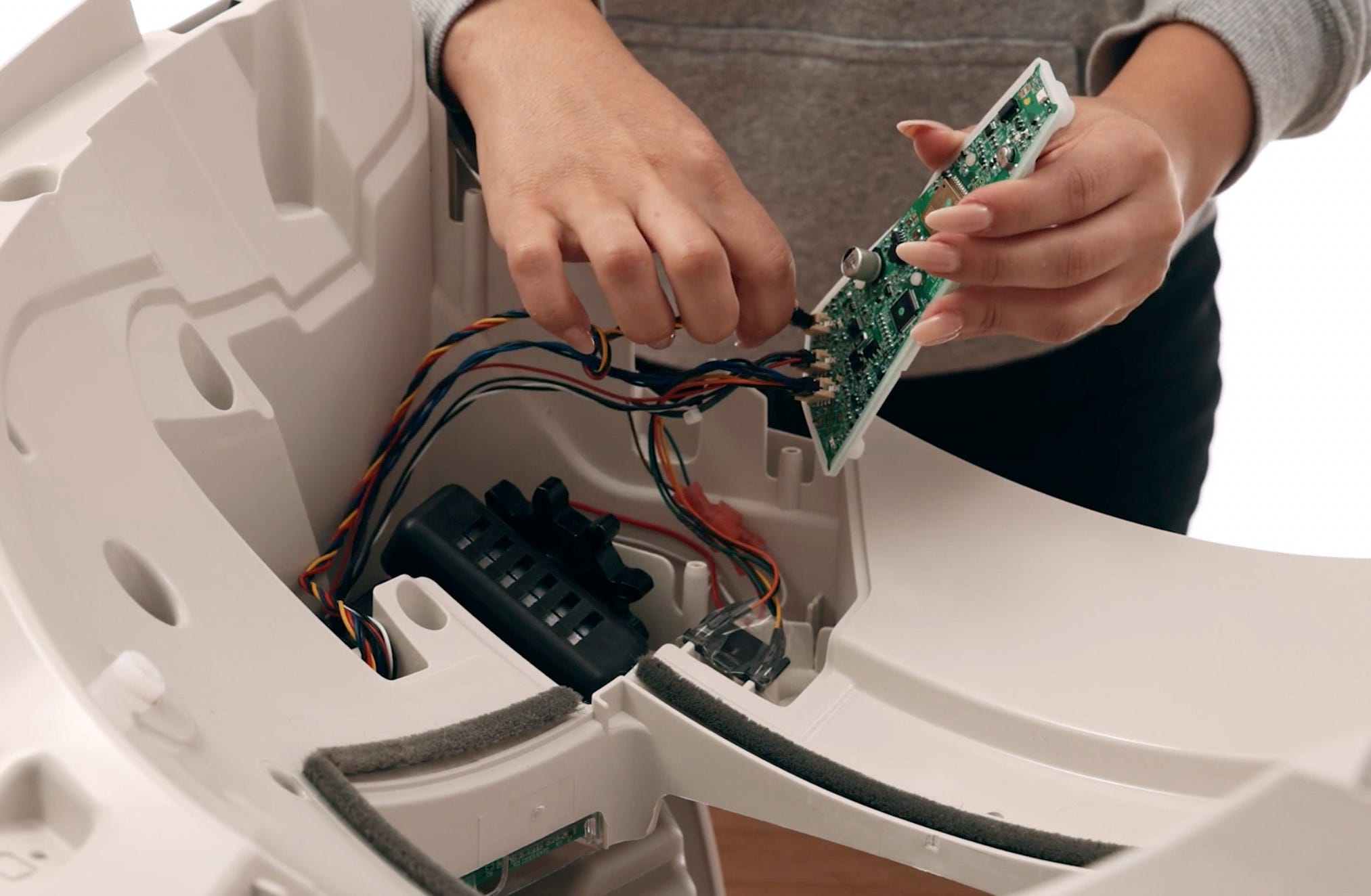
Turn the keypad and circuit board over and unplug the 4-pin connector of the
DFI board.
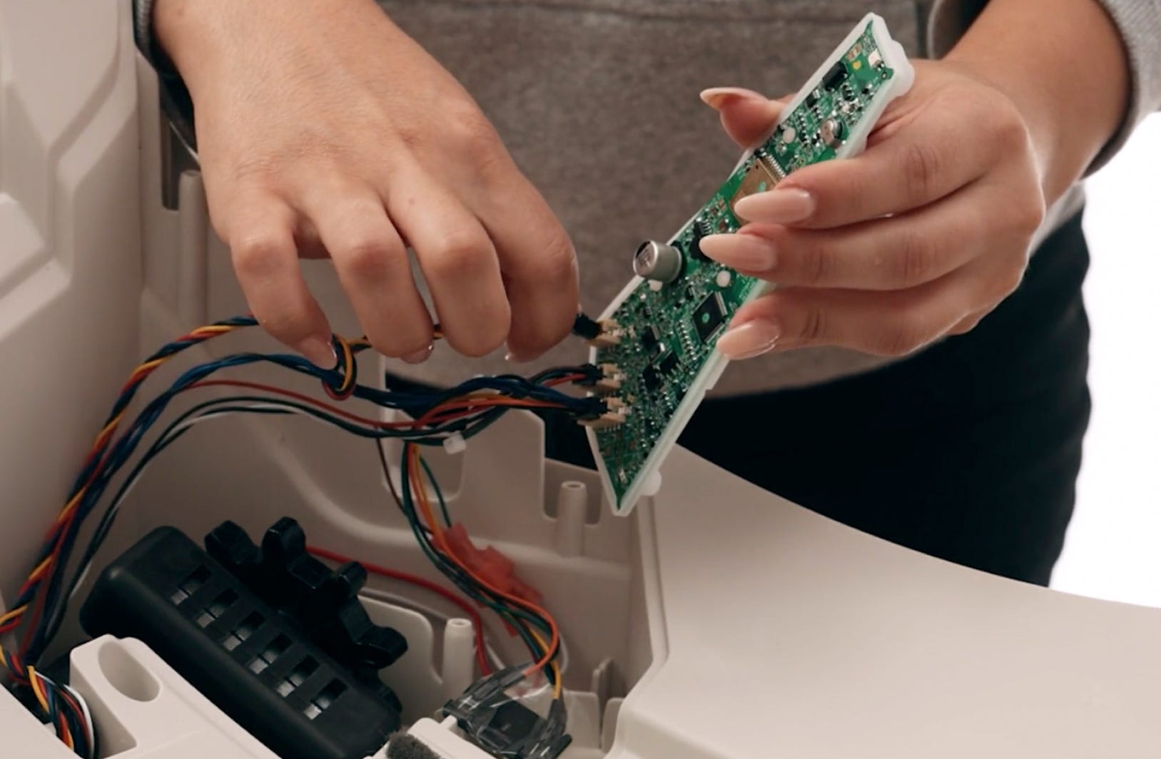
-
The 4-pin connector holds the red, yellow, black, and blue DFI wires. The
circuit board and keypad may be held in place by a piece of tape. If
present, simply remove it; it is not required for reassembly.
-
There are several pieces of tape that hold the DFI wires in the channel and
out of the way of the motor. Free the DFI wires by peeling back the pieces
of tape. You will need to reuse these pieces of tape during the installation
process.
-
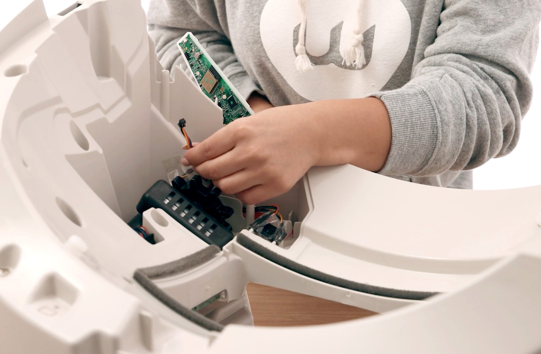
Lift the motor to free the DFI wires from underneath it.
-
Use needle-nose pliers to pull the black wire stopper out of the base and
feed the DFI wires down the hole.
-
To keep the motor, wires, and circuit board in place during the next steps,
temporarily replace the control panel cover and screw it into place using
the 2 screws.
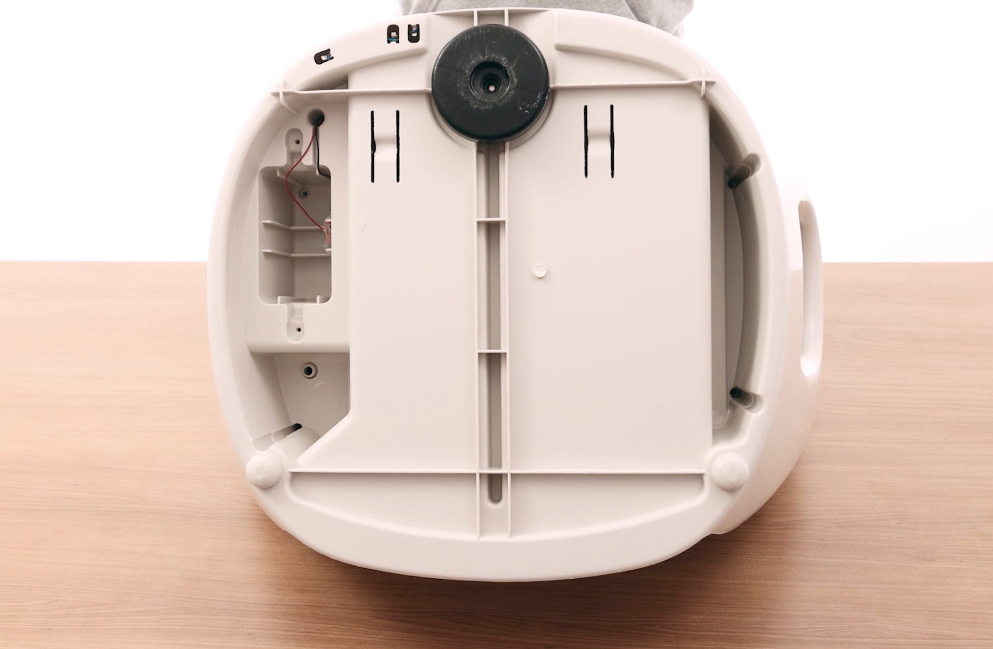
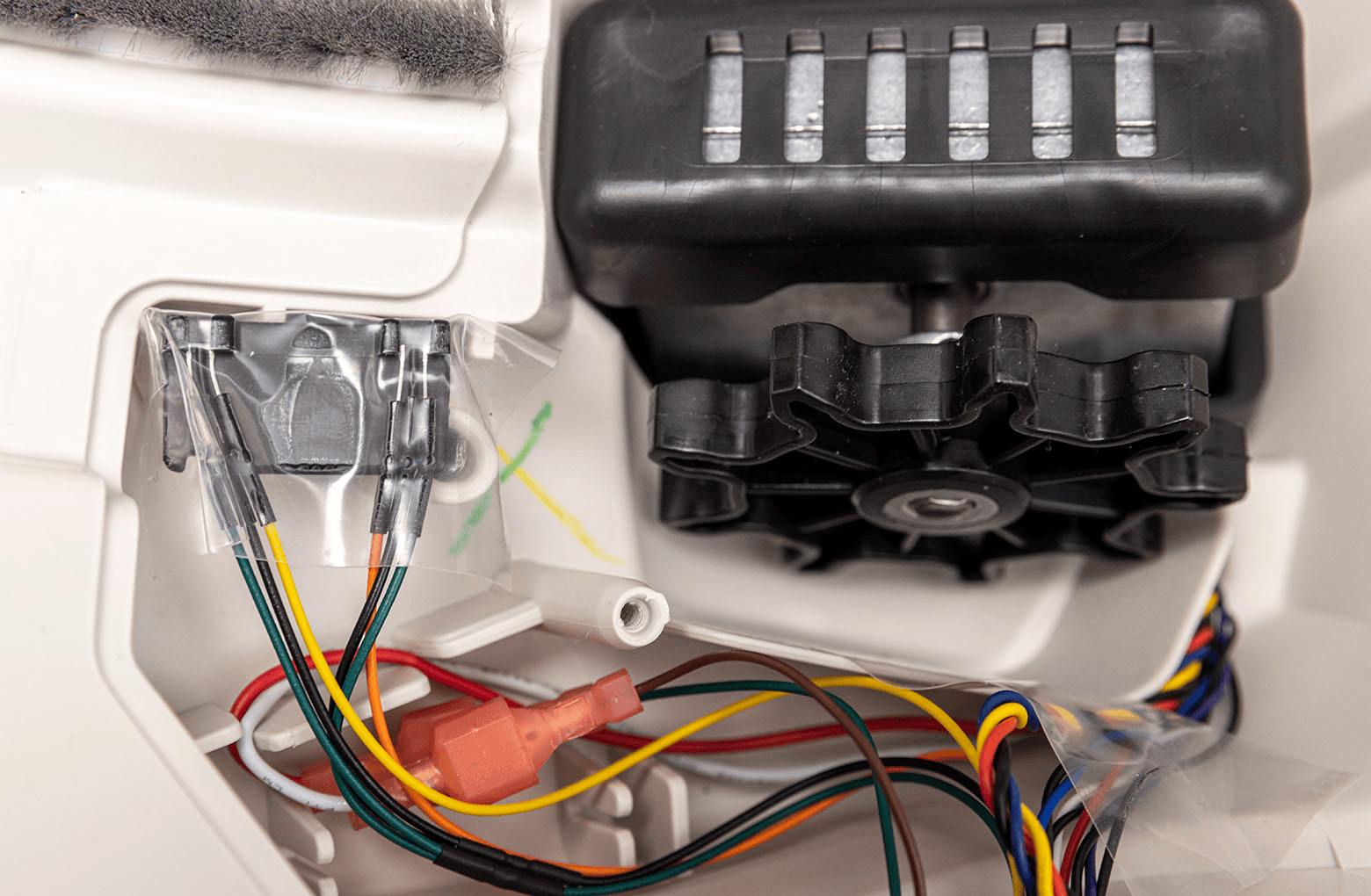
Remove old DFI board assembly and pinch contacts
-
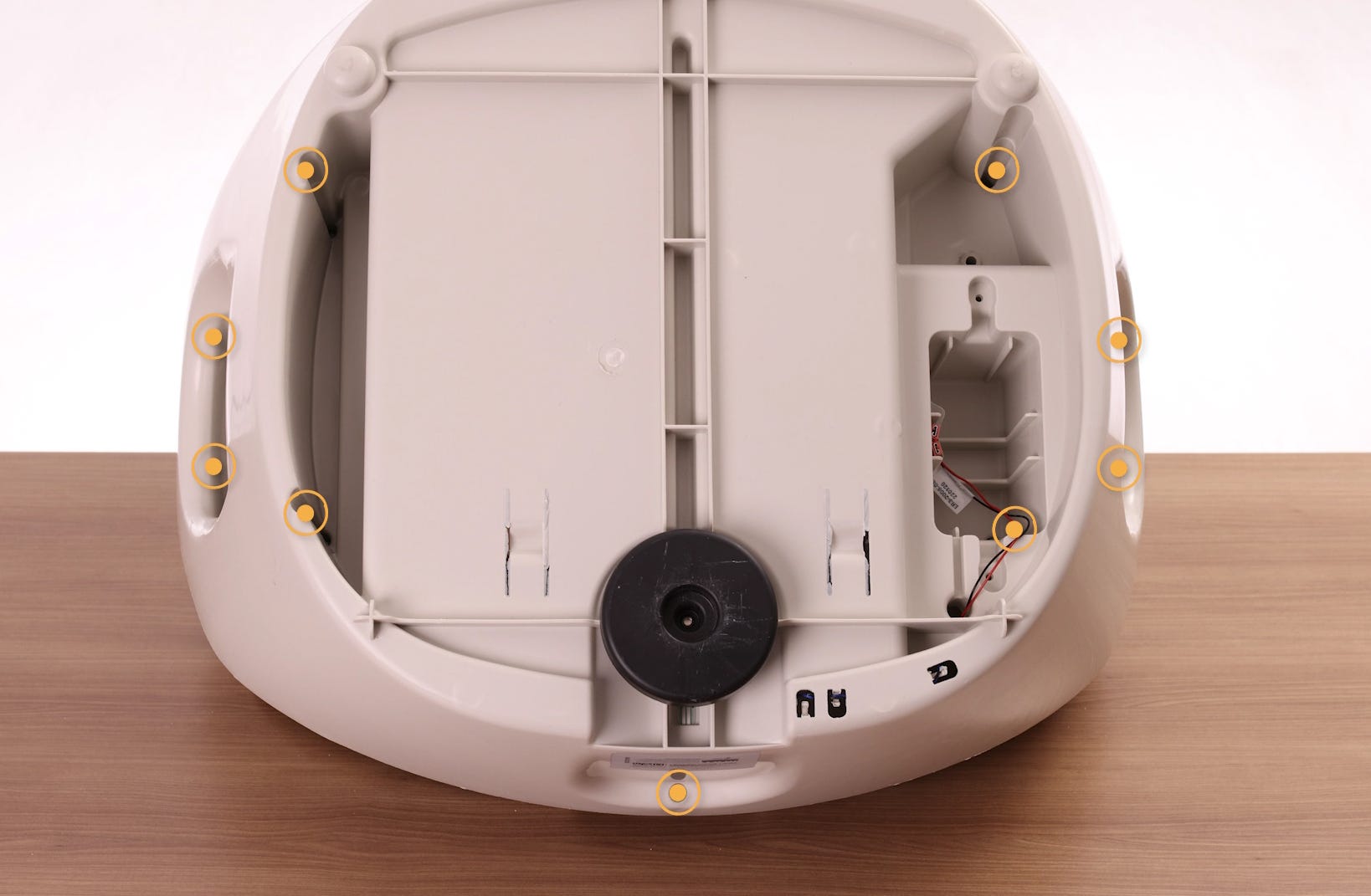
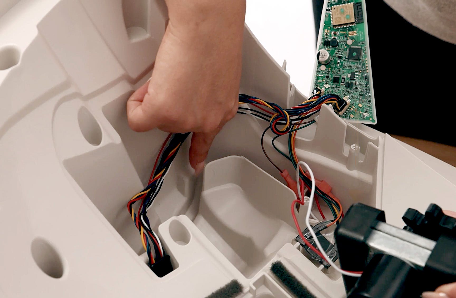
Gently turn the base over and unscrew the 9 screws that attach the two
halves of the base.
-
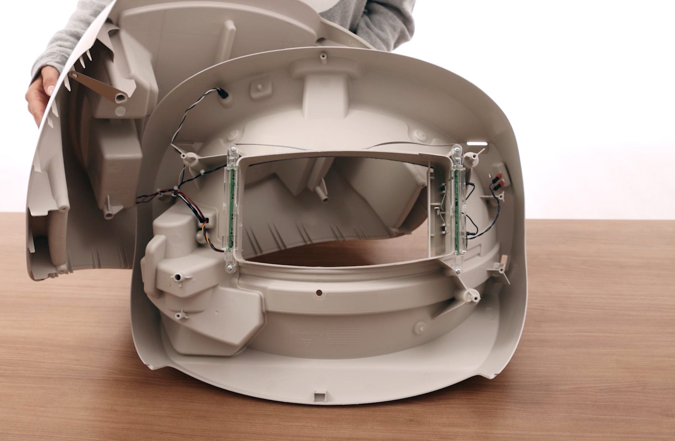
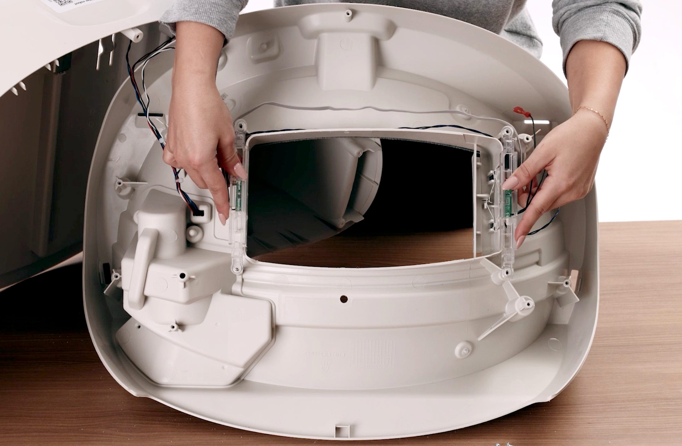
Lift the top half of the base away from the bottom and set it to the right
(remember: there are still connected wires). Locate the DFI boards on either
side of the opening.
-
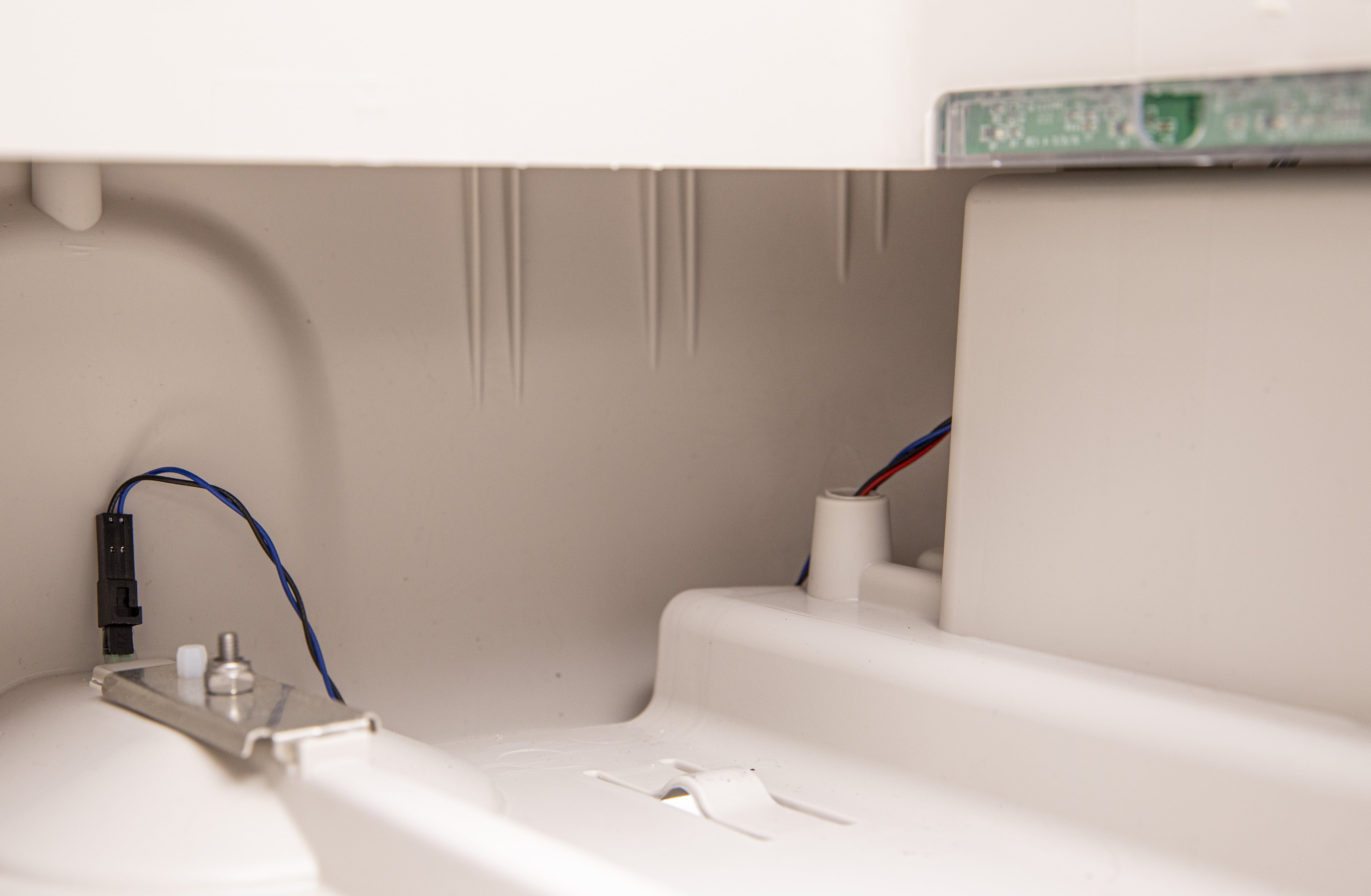
On the right, pull the DFI wires through the hole if they are not already
through.
-
On the left, locate the two black wires. These are connected to the pinch
terminals.
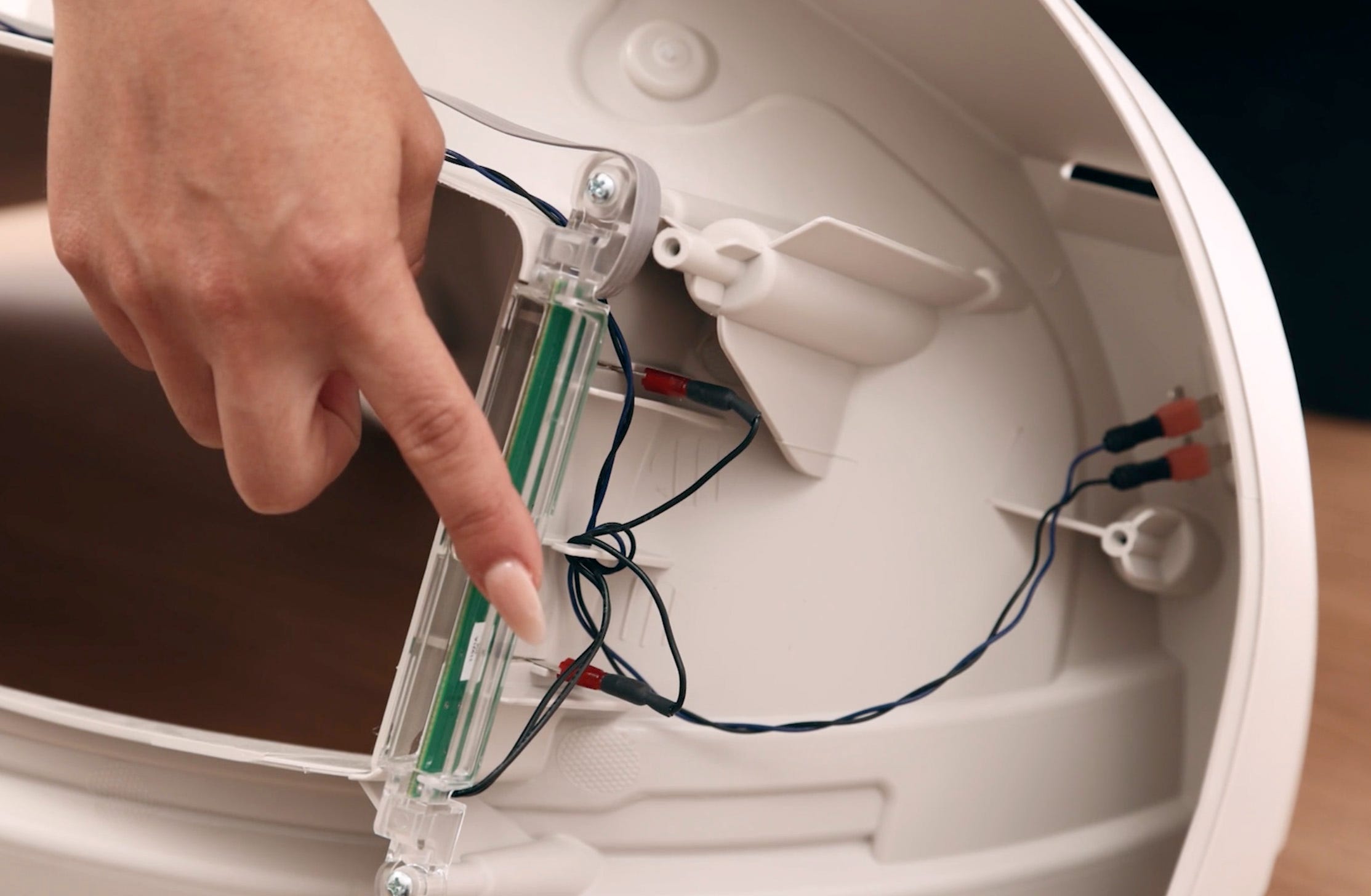
-
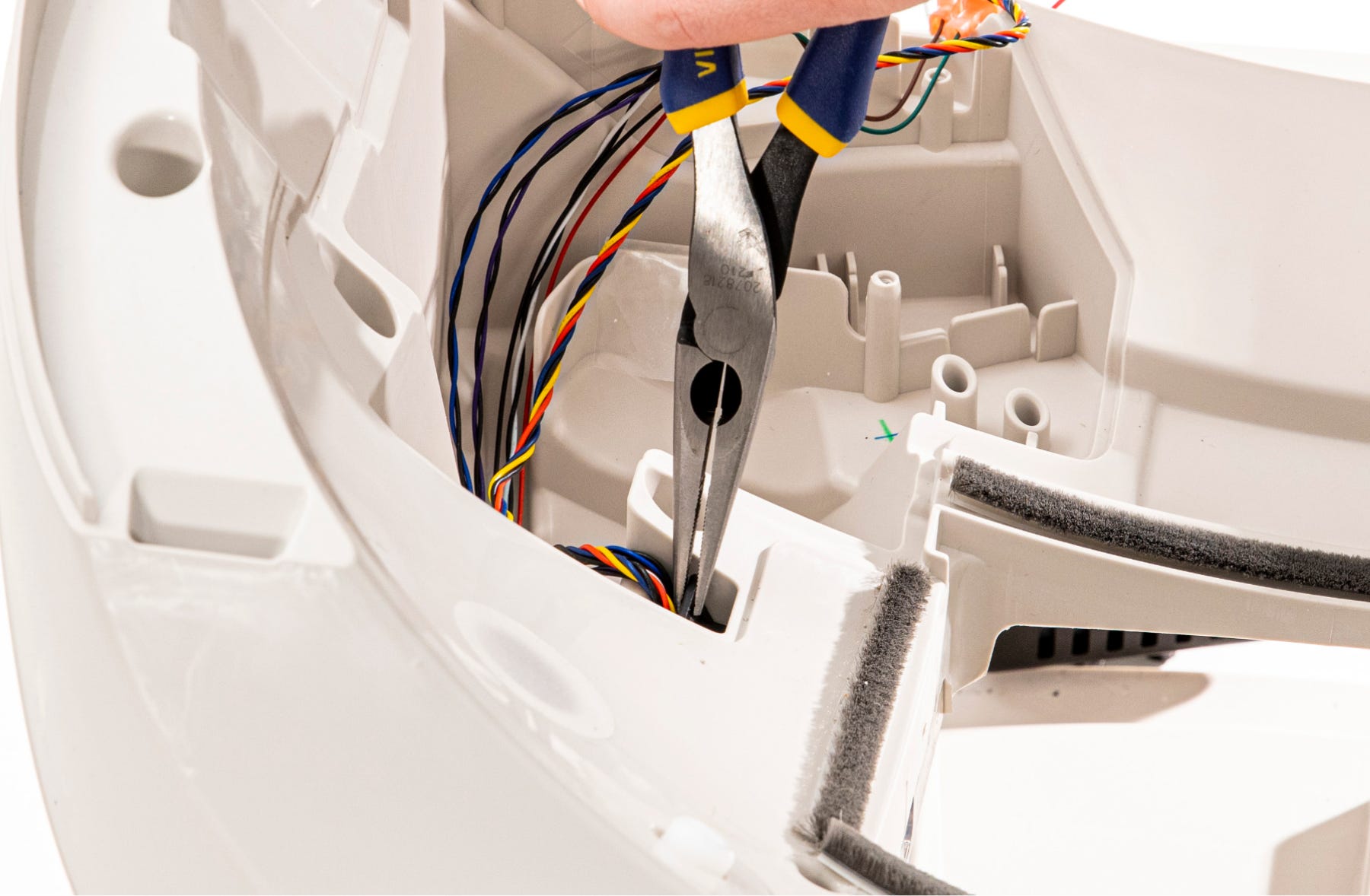
Use needle-nose pliers to separate the connectors from the pinch terminals.
-
On each side, remove the 2 screws that attach the DFI boards to the base.
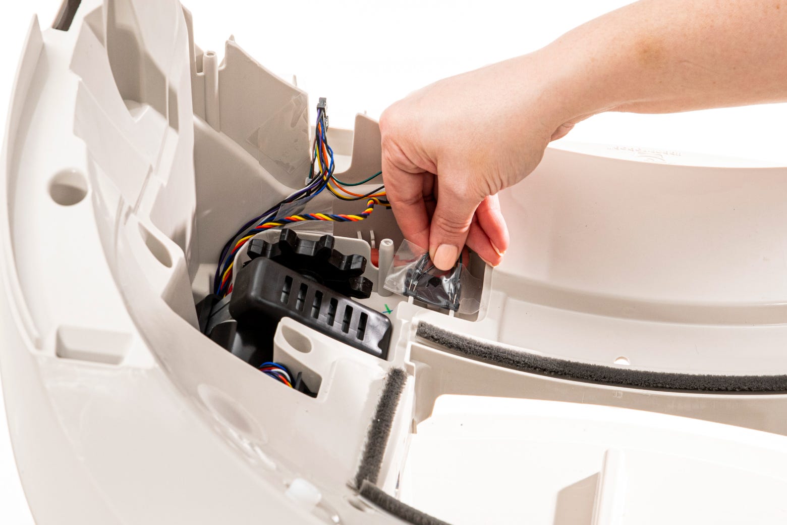
-
On the front edge of the opening, free the gray ribbon cable from under the
hook.
-
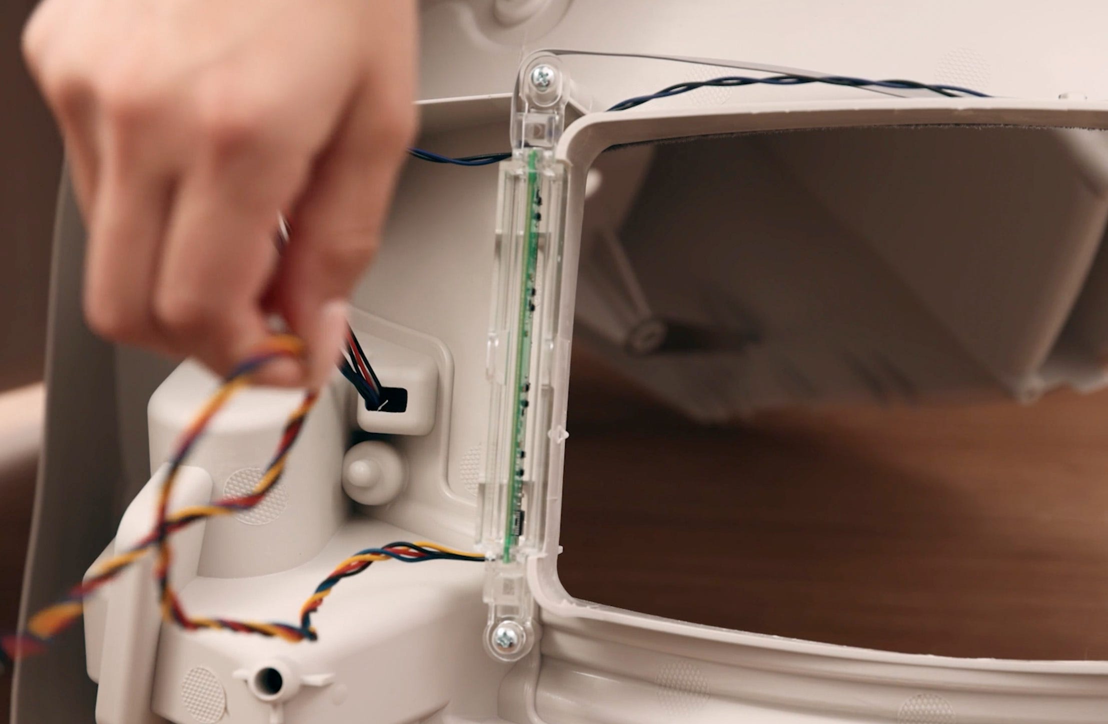
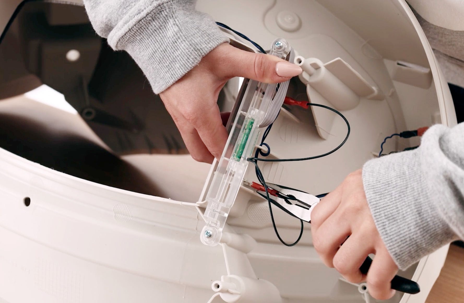
Lift the clear plastic DFI housings off the base and remove the old DFI
board assembly.
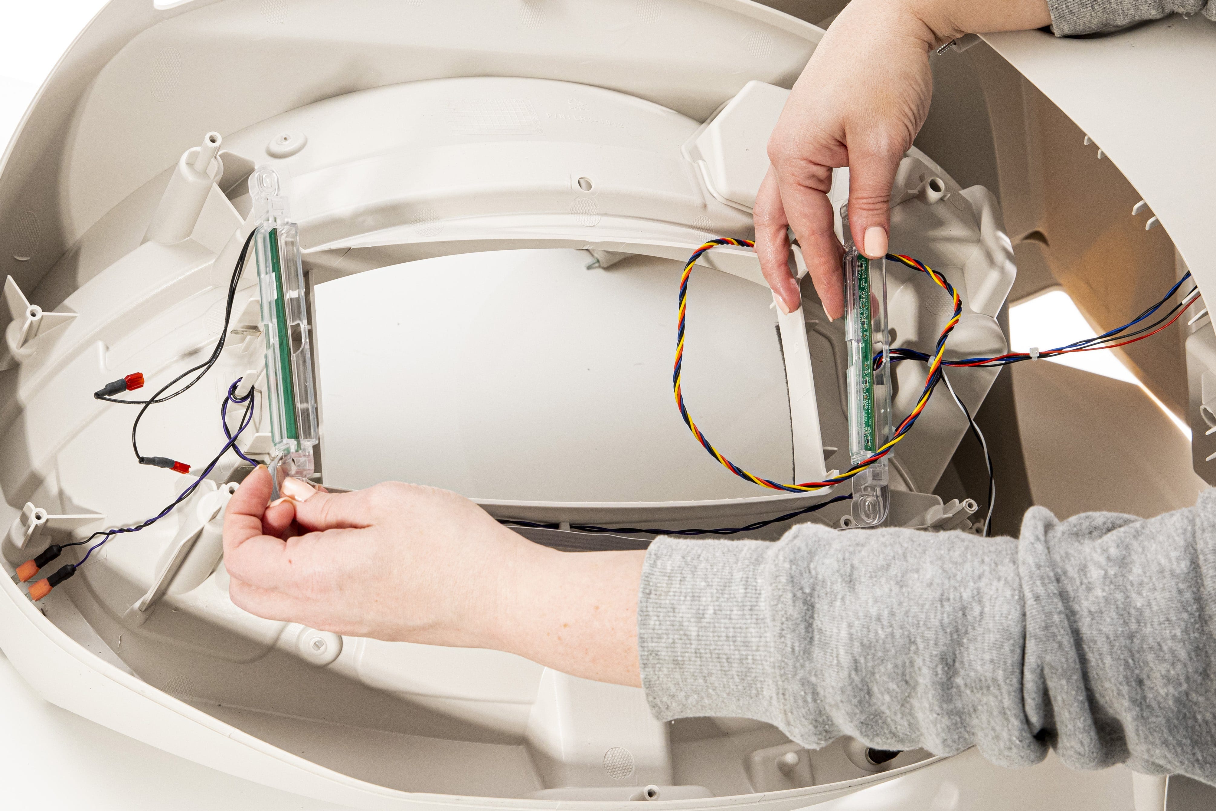
-
Note the placement of the metal pinch contacts.

-
Using needle-nose pliers, gently remove each of the pinch contacts.
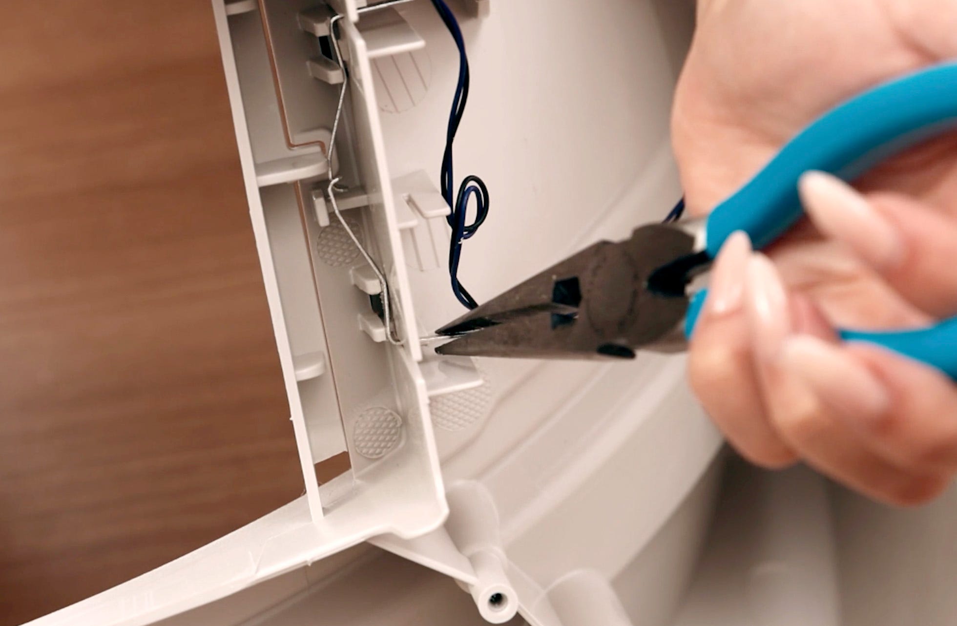
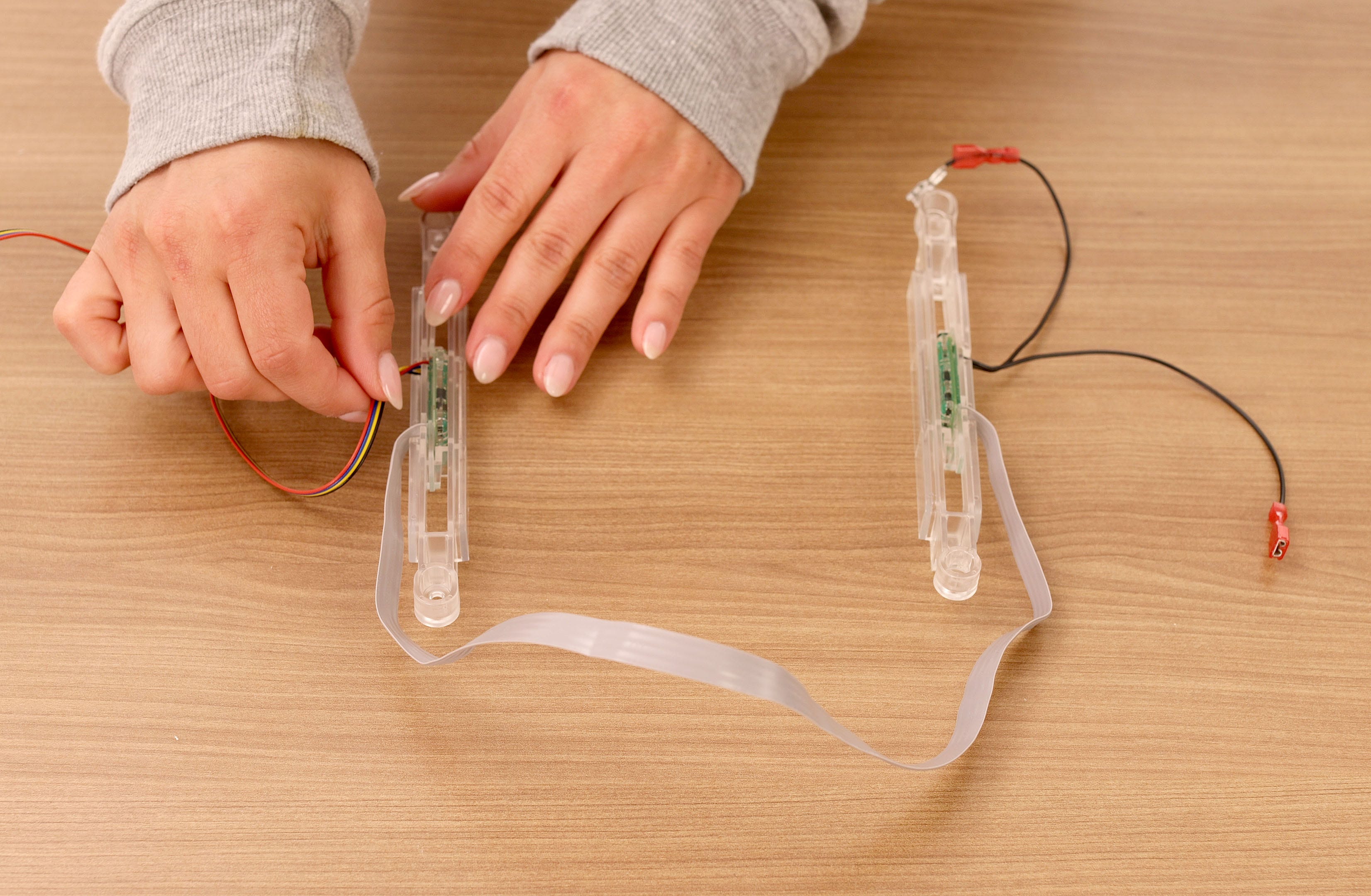
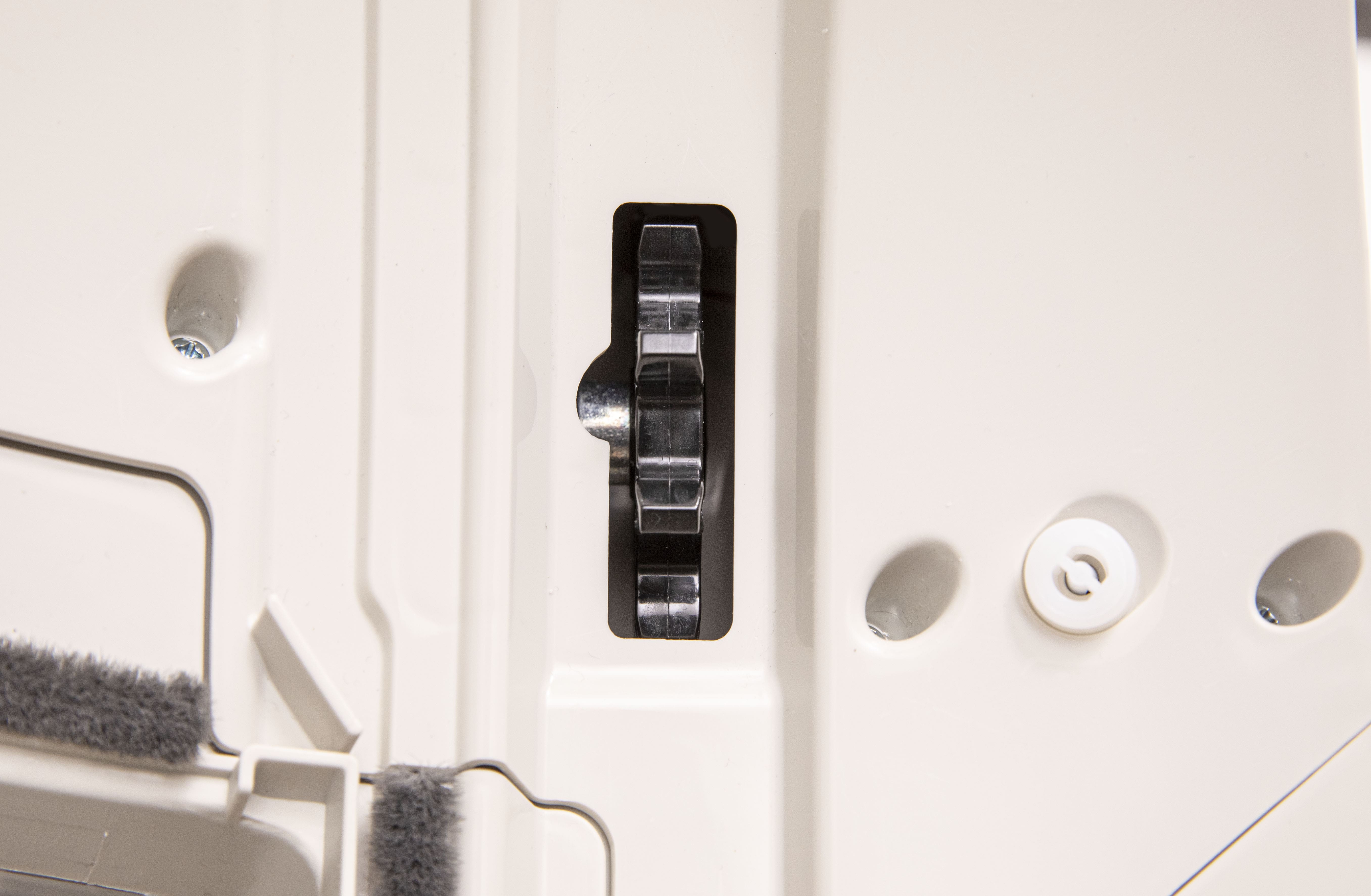
Install new pinch contacts
-
Using needle-nose pliers, position the new metal pinch contacts.
-
Ensure the pinch contacts are fully seated in the slot and that the upper
and lower contacts are overlapping. Both pinch contacts should be touching
each other. A flathead screwdriver can help to gently push them into place.

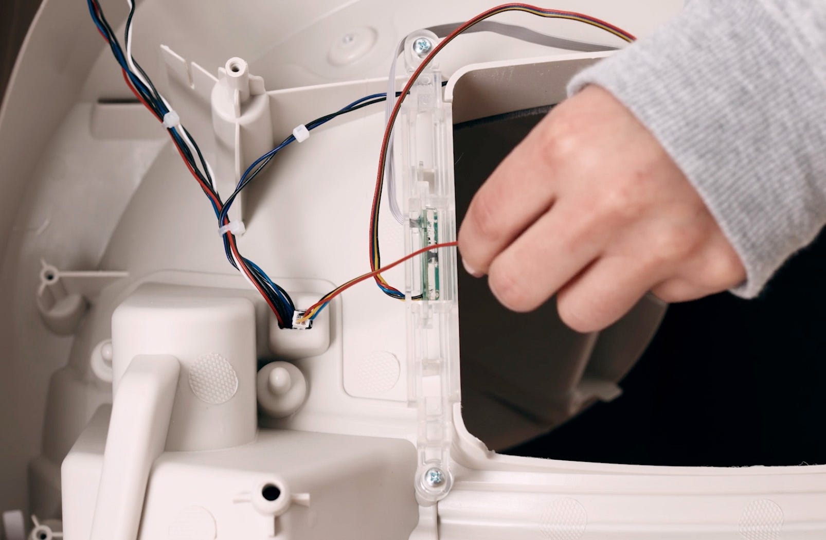
Install new DFI board assembly
-
Orient the new DFI board assembly so that the black wires are on the same
side as the metal pinch contacts.
-
Ensure the DFI boards are installed into the housing first, then installed
in the base facing inward. It is important that the side with the black
sensor is facing inward toward the waste drawer, and the side with the
wiring leading into the interior of the base.
-
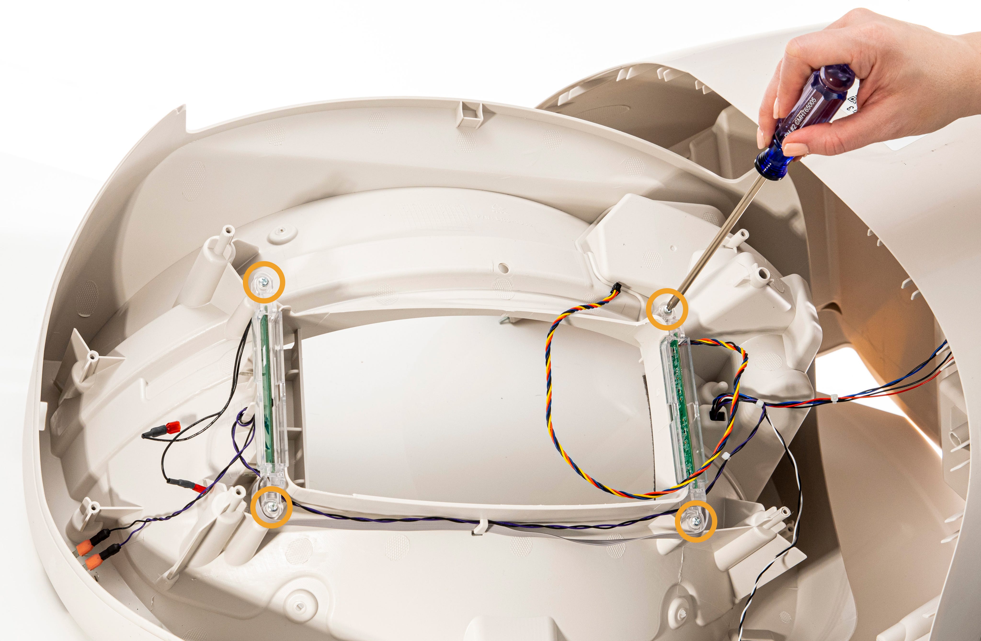
Replace the 4 screws to secure the two clear plastic DFI housings to the
base.
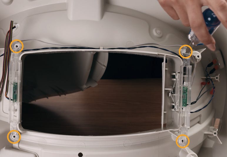
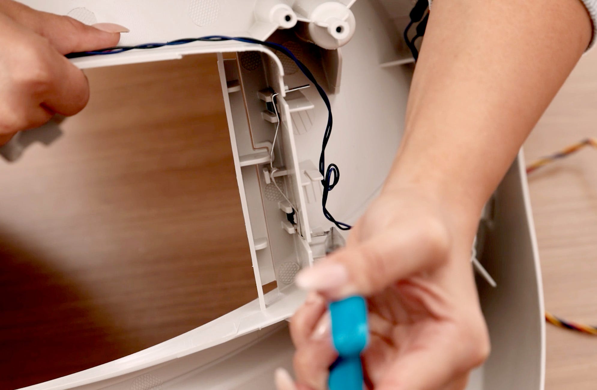
-
Tuck the gray ribbon cable under the retainer clip and over the wires that
are already there, making sure that the wire sits between the corner of the
waste port and the screw boss.
-
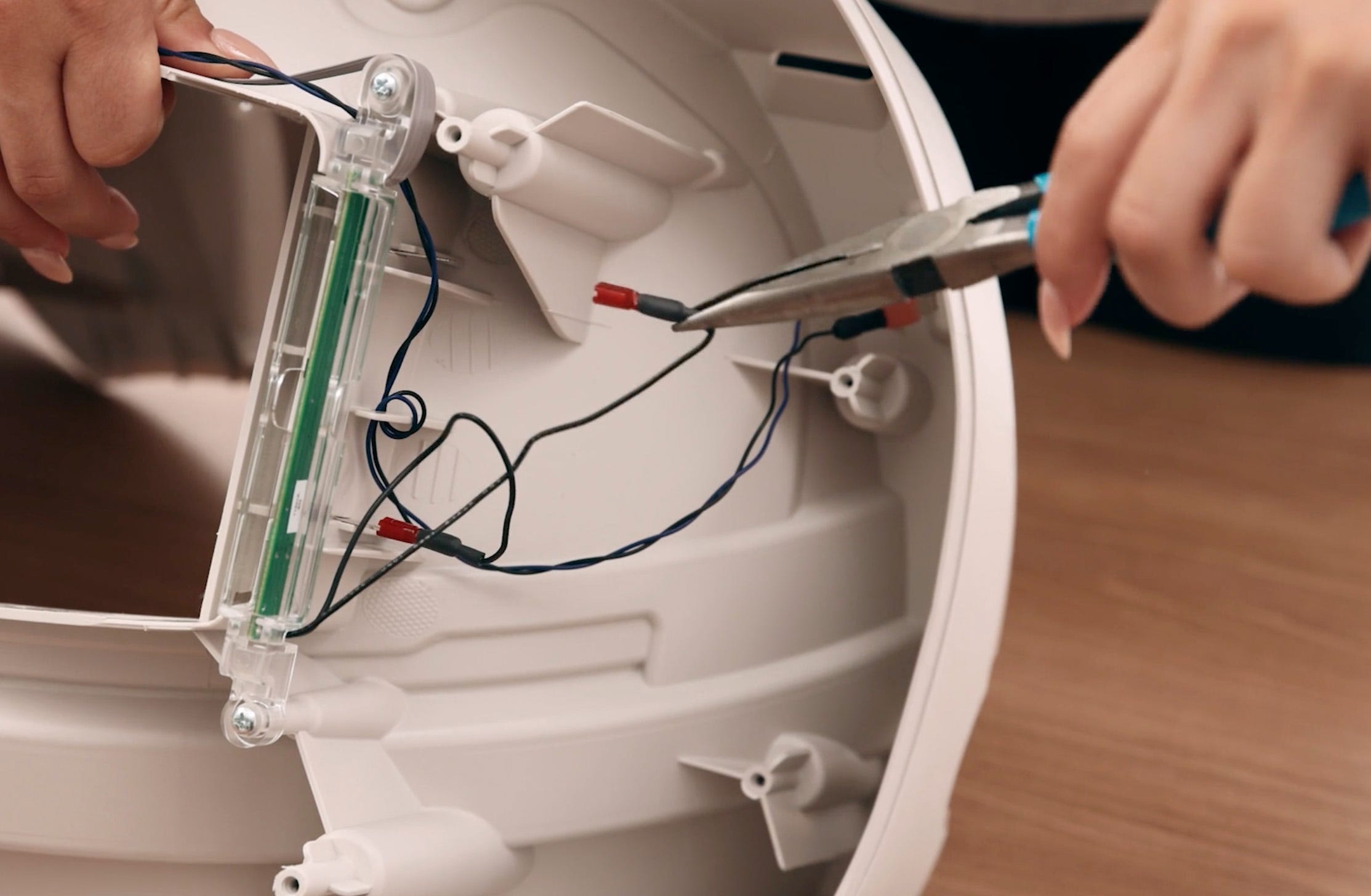
Reconnect the black wires to the metal pinch terminals in any order. (The
wires are not specific to a terminal.) Please note, these need to be
securely attached to ensure a sound connection.
-
To reduce stress on the component, it is best to place a finger opposite
the connector as you apply pressure. Make sure the metal terminal is
inserted into the metal connector and not accidentally pushed into its
red case.
-
To reduce stress on the component, it is best to place a finger opposite
the connector as you apply pressure. Make sure the metal terminal is
inserted into the metal connector and not accidentally pushed into its
red case.
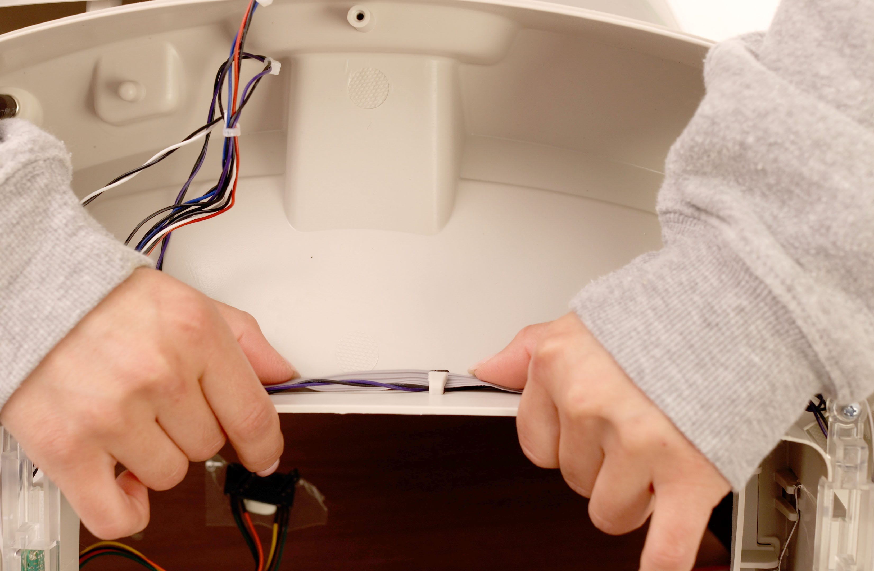
-
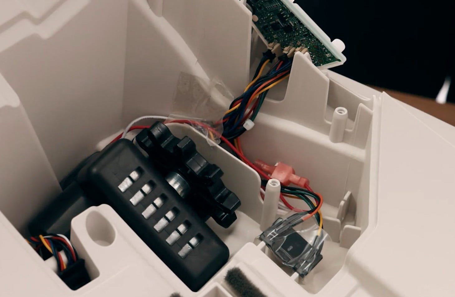
On the side of the base where the control panel is located, feed the DFI
wires through the hole you accessed earlier. You will need to reconnect this
4-pin connecter to the circuit board in the final steps. The 4-pin connector
holds the red, yellow, black, and blue DFI wires.
Reassemble base
-
Replace the other half of the base, making sure the top and bottom halves of
the screw bosses align and that the edges, or seams, are aligned so that
there is no gapping or overlapping.
-
BEFORE tightening any screws, carefully rotate the base and look through the
front where the waste drawer would be. Make sure the wires are placed on the
interior of the screw boss, so they do not get in the way of the waste
drawer. You may have to separate the base to reposition the wires.
-
Once everything is seated correctly, tighten the 9 screws. Be careful not to
overtighten.
-
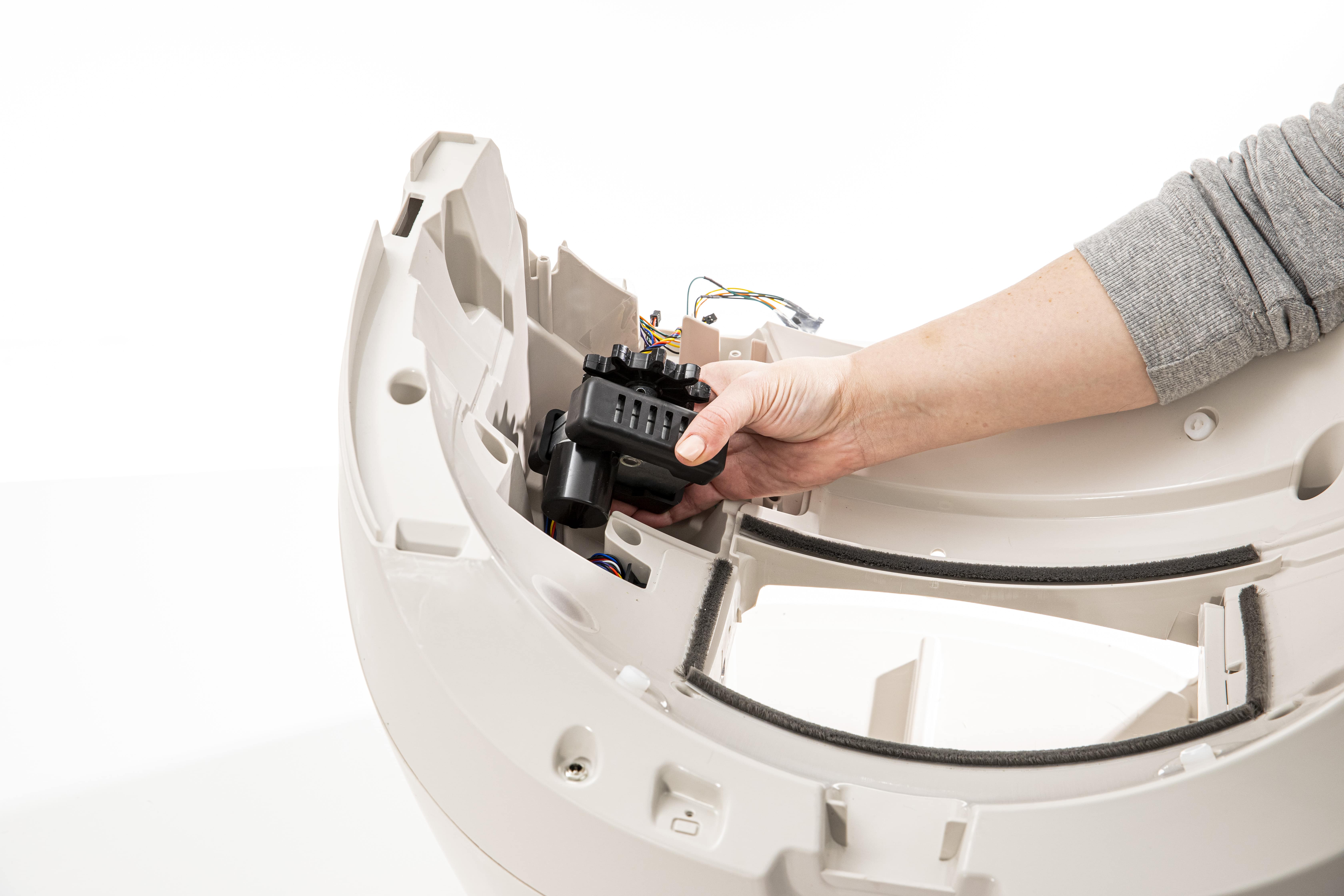
Replace the black wire stopper; use pliers if needed.
-
Gently lift the motor to seat the DFI wires in the channel below it, and
continue placing the wires in the channel in front of the motor. Reapply any
tape that was removed. When securing, make sure the wires go under the motor
and motor isolator.
-
Locate the DFI wires that you pushed through the hole.
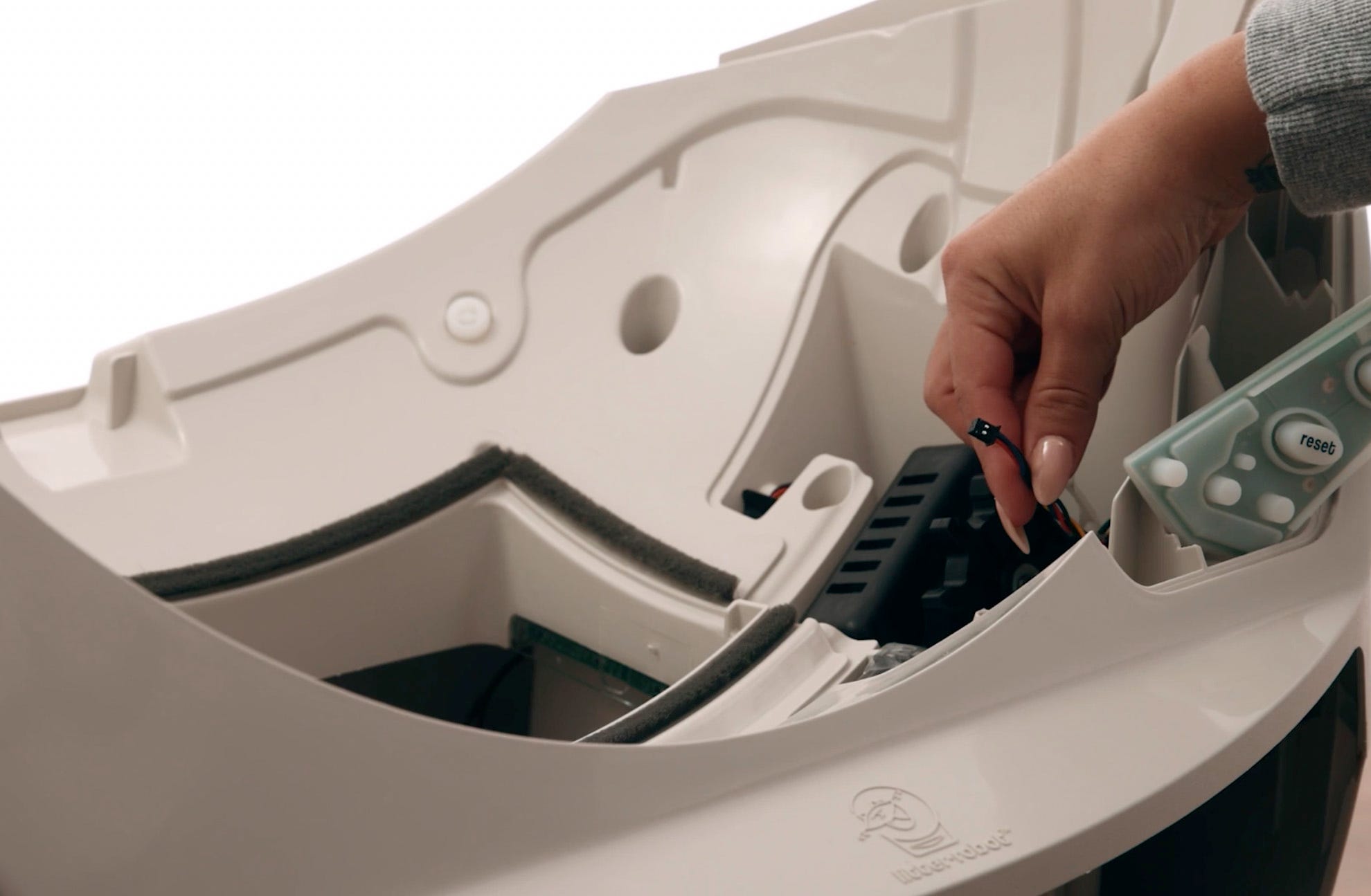
-
Reconnect the 4-pin connector to the circuit board in the bottom left
corner. The connector will only fit one way; if you feel resistance, turn it
over and try again.
-
Replace any tape that will help hold the board in place. Secure the tape
over the wires to keep them in the channel and out of the way of the motor
and gear. Reseat the motor.
-
Double-check that the position sensor is oriented correctly. When standing
in front of the robot, the bundle of wires that includes a YELLOW wire
should be on the left. The bundle of wires that includes an ORANGE wire
should be on the right.
-
Reassemble the control panel cover onto the circuit board and keypad by
pushing the keypad buttons back through the cover.
-
Make sure to keep the keypad wrapped around the edges of the circuit
board.

-
Make sure to keep the keypad wrapped around the edges of the circuit
board.
-
Look through the opening where the black gear protrudes and make sure no
wires are visible. If wires are visible, remove the control panel cover,
tuck them into the wire channel, and secure them with a piece of tape.
-
Once in position, the edges of the control panel cover should rest flush
with the base.
-
Attach the control panel cover by tightening the 5 screws. Do not
overtighten.
Reassemble Litter-Robot
-
Replace the waste drawer.
-
Replace the globe, ensuring it is positioned correctly. Visually check that
the large gear that runs around the globe is sitting in the track on the
base.
-
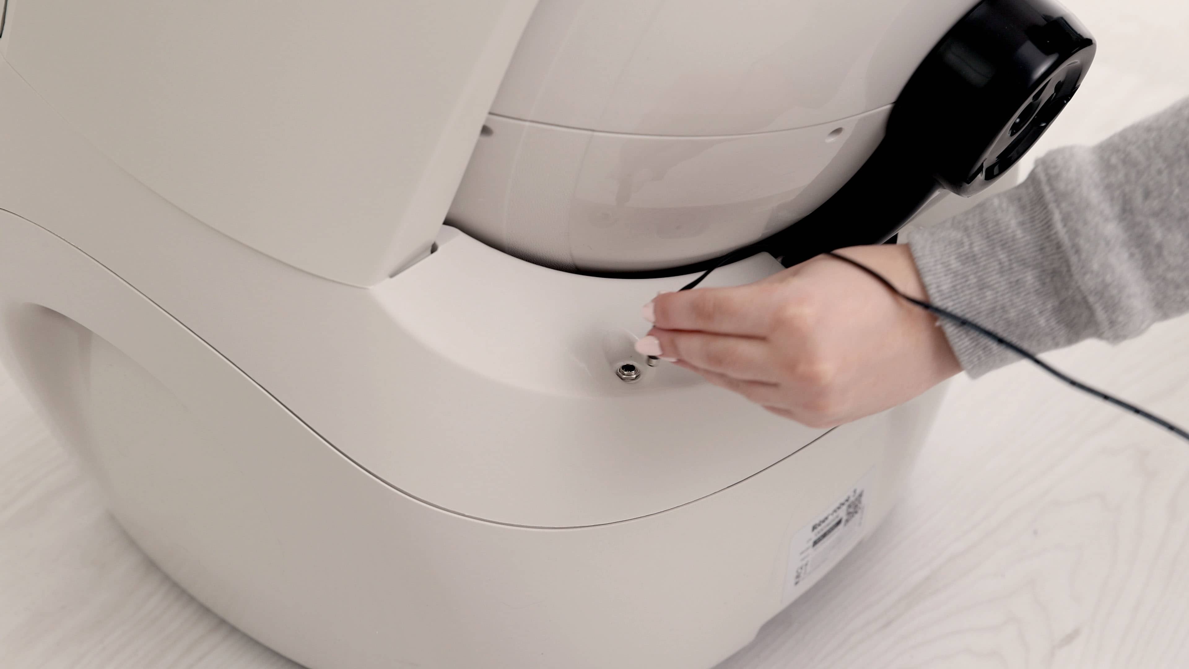
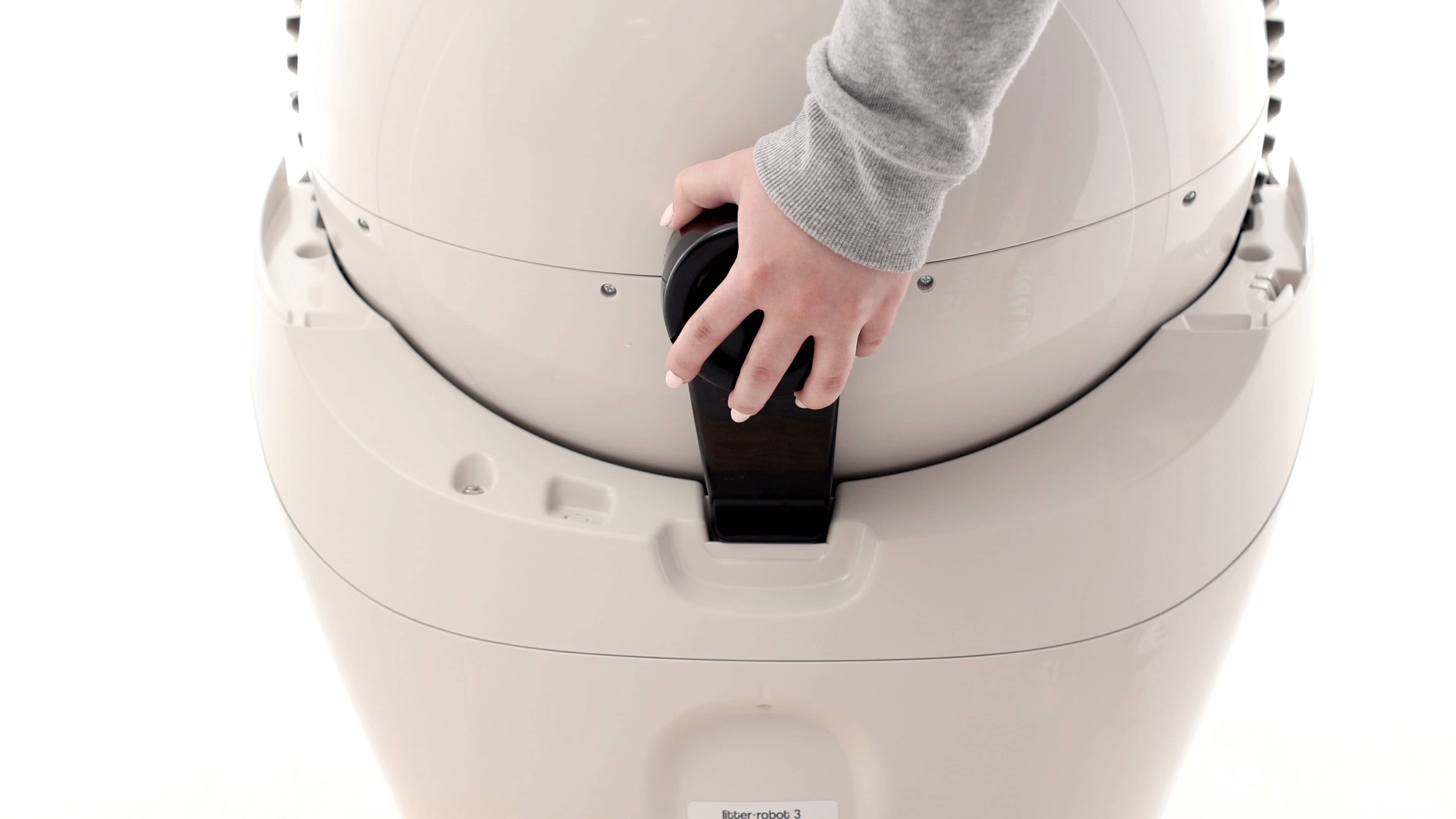
At the back of the globe, turn the black key into the key pocket.
-
Replace the bonnet, sliding the tabs on both sides into the slots in the
base.
-
Rotate the bonnet forward, aligning the tabs with the corresponding slots in
the base. Snap the bonnet securely into the base.
-
Plug the power plug into the base.
-
Press the Power button to turn the unit on.
-
Once the initial clean cycle is complete, the unit should return to the home
position displaying a blue “ready light” status.
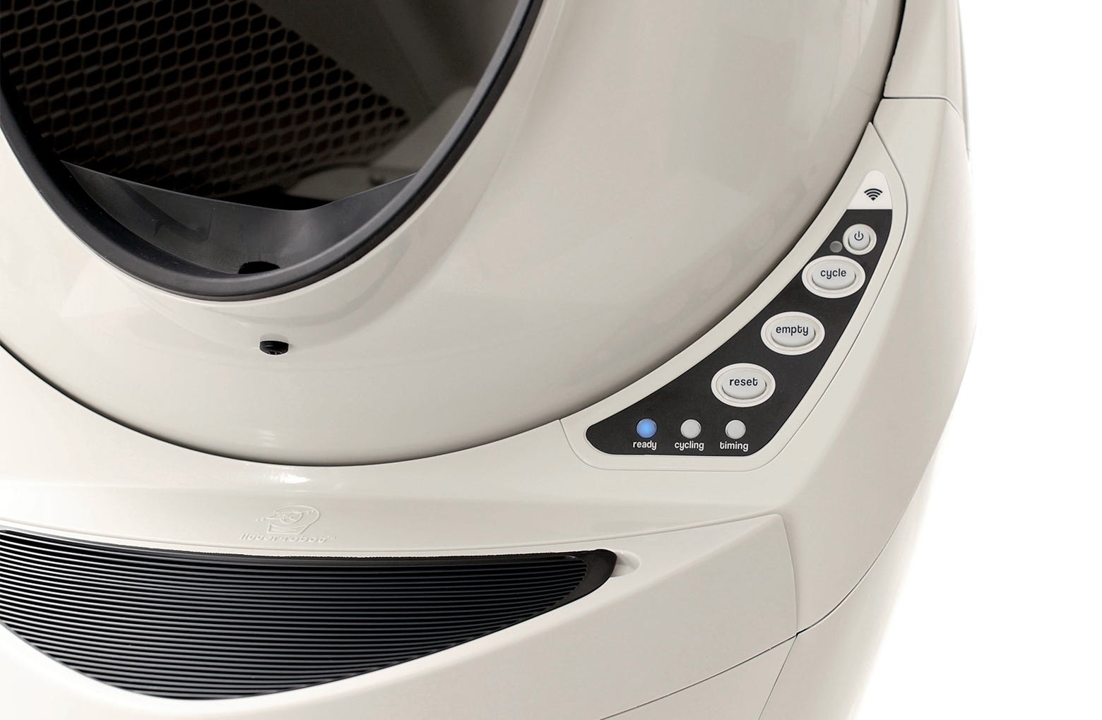
- If your unit does not cycle or does not cycle properly, review your installation.
If you’re getting three flashing lights, it is most likely due to the position sensor being out of place. Follow the steps in our Litter-Robot 3: All three lights flashing (Globe position fault) guide to inspect the position sensor.
Didn't find what you're looking for?
Live support available Mon-Fri: 9AM-9PM EST and Sat-Sun: 9AM-5PM EST, or submit a ticket anytime.